Driving BLDC Motors with Six-Step Commutation
November 22, 2022
I have an ODrive on hand, but going through the documentation and the process of running it with various BLDC motors has been quite tedious. After all this configuration, I feel confident enough to write my own code to drive it. Conveniently, I also have several STM32 test boards at hand. I grabbed an STM32F405RGT6 development board and successfully got the motor running on the ODrive using the Six-Step Commutation method.
Here's a breakdown of the entire process and some key points.
Materials
- Makerbase Odrive 3.6 56V Board
- X2212 Motor + TLE5012 Encoder
- STLink v2
- DC Power Supply
Result Video
TLE5012 Encoder A/B/Z Signal Processing
The TLE5012 is a magnetic encoder capable of outputting standard A/B/Z signals. To achieve precise commutation for the motor, we need to decode its position and direction using the A/B/Z signals.
A/B Quadrature Signal Processing
The TLE5012 provides quadrature encoding output through its A/B pins.
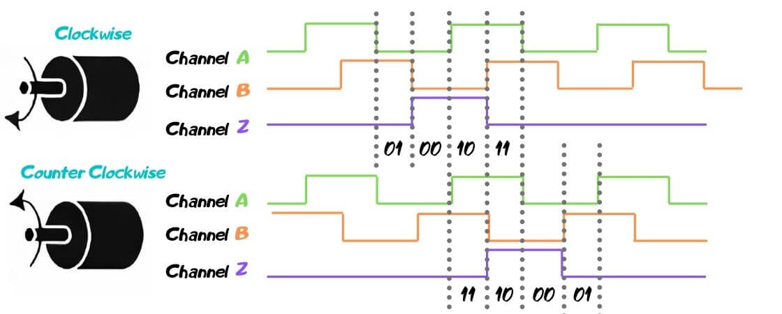
By analyzing the state transitions of the A/B quadrature encoding (00/01/10/11), we can perform incremental counting, which also allows us to determine the motor's rotational direction. Using the STM32 Timer, we can easily obtain this information.
// Connect a rotary encoder to pins A0 and A1.
let rotary_encoder_pins = (
        gpiob.pb4.into_floating_input(), gpiob.pb5.into_floating_input());
let rotary_encoder_timer = dp.TIM3;
let rotary_encoder = Qei::new(rotary_encoder_timer, rotary_encoder_pins);

let mut current_count = rotary_encoder.count();

loop {
    let new_count = rotary_encoder.count();
    info!("curr: {}, new: {}", current_count, new_count);
    ...
}
Encoder Z Signal Processing
The Z signal is a periodic pulse that generates a rising and falling edge once per rotation:
- The rising edge is used to mark the motor's "zero point," enabling multi-turn position resetting.
- For BLDC commutation, the Z signal trigger can be used to calibrate the phase.
We can capture Z signal changes through interrupt triggers. Here's an example of the interrupt trigger code. This code is somewhat verbose, so we won't include it here in detail. In simple terms, the Z signal's Rising/Falling edges are captured by interrupts, allowing us to perform further processing. However, this code is just a demo and doesn't perform any actual operations.
Six-Step Commutation
MOSFET For Motor Driven
The ODrive circuitry is essentially similar to the H-bridge driver used in DC motors. Each end of a motor coil is controlled by two MOSFET switches, referred to as the H and L ends. A key principle here is that the H and L ends of the same coil must not be switched on simultaneously, as this would create a short circuit and should damage the hardware. This is a crucial consideration when writing code. With this setup, there are 6 MOSFETs to control the power flow. Additionally, by adjusting the PWM duty cycle, we can control the magnetic field generated in a given direction. Thus, 6 PWM inputs are required to control the circuit.
Understanding How the Rotor is Driven
Let's break it down: when two different coil H/L ends are energized, such as AH/BL, the direction of current flow through the coils generates forces. These forces combine into a resultant force. There are a total of 9 possible combinations of AH/BH/CH ~ AL/BL/CL, excluding the 3 combinations (e.g., AH~AL) that would result in a short circuit. This leaves six valid combinations. When equal forces are applied, the resultant force theoretically points to one of six directions around the circle, spaced at 60° intervals.
Six-step commutation simply alternates these six magnetic pole directions with equal force, generating a torque that drives the rotor.
Beyond Six-Step Commutation
More precise methods involve determining the rotor's current position and creating a magnetic pole direction exactly opposite to the rotor's current magnetic pole. This can be done using two or even three coil ends. This method maximizes torque based on the rotor's inertia. Furthermore, by adjusting the PWM duty cycle at each terminal, the magnetic force magnitude can be controlled, allowing for optimal torque output. Such fine control is typically achieved using PID algorithms.
Video Reference
I haven't come across particularly good YouTube videos explaining this process, but this Chinese video might be helpful.
Challenges and Observations
One key issue is the inevitable manufacturing imperfections in the motor, such as slight discrepancies in coil winding. These small errors can influence the direction and magnitude of the force generated, creating complications in motion control. I need to investigate this further to understand how to best synchronize the motor and driver. Based on these findings, we can determine how to compensate for hardware inaccuracies through software adjustments. This will clarify the level of hardware precision loss and the software solutions needed to address it.
Algorithm Requirements and Implementation on STM32
To implement six-step commutation or other advanced motor control algorithms, several key algorithmic components are needed. STM32 microcontrollers provide robust support for these tasks, making them ideal for motor control applications.
Algorithm Approach
In this experiment, we will temporarily avoid using the encoder output discussed earlier to determine the rotor position for closed-loop control. Instead, based on the above discussion, we will implement six-step commutation. Specifically, we will cycle through the following sequence: AH/BL => AH/CL => BH/CL => BH/AL => CH/AL => CH/BL. For each step, we will introduce sufficient delay to ensure the rotor aligns with the magnetic field's defined direction before moving to the next step. Of course, this method will result in a clicking noise, but it is adequate for experimental verification of the concept. The algorithm can be summarized as follows:
- After initialization, enter a loop.
- Identify the current step, turn off the PWM signals from the previous step, and activate the PWM signals corresponding to the current H/L step.
- Wait for sufficient time to allow the rotor to align with the desired position.
Now, let's move into the implementation.
Implementation on STM32
To meet the requirements above, we need STM32 support for generating a sufficient number of identical PWM signals. Based on our discussion, we need 6 PWM signals. Referring to the ODrive schematic, the corresponding relationships are as follows:
- AH/BH/CH: PA8/PA9/PA10
- AL/BL/CL: PB13/PB14/PB15
Exploring STM32 Timers
Due to my initial lack of familiarity with STM32 timers, it took me a long time to figure this out. Eventually, I found the following code in the ODrive project and inferred that each STM32 timer can provide up to 8 identical PWM outputs:
sConfigOC.OCPolarity = TIM_OCPOLARITY_HIGH;
sConfigOC.OCNPolarity = TIM_OCNPOLARITY_HIGH;
For example, if we connect AH/AL to two complementary outputs of the same PWM channel, their behavior will be identical because the timer (counter) determines when to output a high level. By setting the complementary output to also be high when the counter is exceeded, AH/AL will produce identical signals.
STM32 timers are extremely powerful, and exploring their full functionality is beyond the scope of this discussion. However, understanding this principle simplifies the implementation. You can refer to my motor-exp code for the detailed implementation.
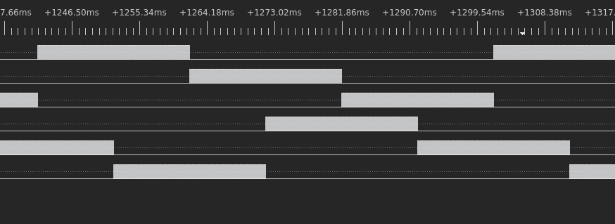
PWM Signal Verification
After connecting the outputs of this code to my logic analyzer, I obtained the following results:
 Two PWM Signals Details
 Six PWM Signals
Running the Motor
After confirming the correctness of the PWM outputs, I flashed the code onto the STM32 chip on the ODrive. After powering it on and rebooting, I successfully observed the X2212 motor running smoothly. Below is the demo video again.
Six-Steps Commutation Demo
Questions
Actually, there are still many questions regarding driving a motor, especially FOC and more. For now, I won't elaborate on them here. I'll take my time to figure them out step by step in the future.
Summary
This post demonstrates how to implement Six-Step Commutation to drive a BLDC motor using an STM32F405RGT6 development board, bypassing the typical configuration-heavy process associated with ODrive. The project explores TLE5012 encoder signal processing, PWM-based motor control, and STM32 timer functionality. A practical experimental setup is presented, showcasing the fundamentals of BLDC commutation, algorithm design, and STM32 capabilities.